
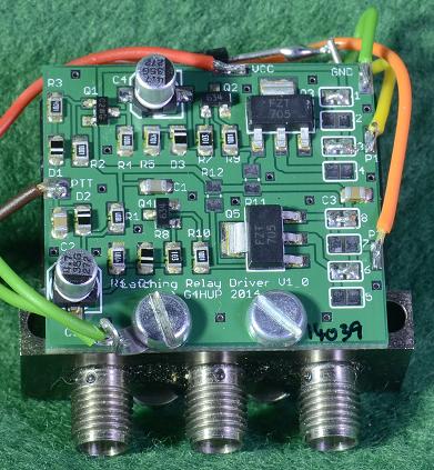
Like the PAT board, the Latching Relay Driver has been introduced as an introductory SMD assembly project. It is a little more complex and compact than the PAT board, but nevertheless it is well within the capabilities of first time SMD users.
The Latching relay Driver converts polarised latching relays (which are not tremendously useful to amateurs) into failsafe (or PTT) drive types – which are much more useful! The PCB has been sized to fit to the side of the small SMA types, which makes installation very easy.
The circuit will operate on voltages up to 28v – so it will cope with those rarely found 12v ones, and the much more common 28v relays. The output devices are 120V Vc-e 4A transistors, so it will happily drive the larger N type latching change over and transfer relays, as well as the small SMA ones. This circuit is not intended to drive 50v relays – the two pulse forming capacitors (C4 and C5) are not rated for this voltage, and could fail.
 |
Driver Configuration
Latching relays come in two types
– ‘low side common’, in which each coil must be driven from a positive source, with the cold ends commoned to 0V;
– and ‘high side common’, where the hot end of each coil is commoned together to the supply rail, and the switching voltage is applied to the cold ends of the coils.
To cope with these two types the Latching Relay Driver PCB has 8 solder jumper links, arranged in a group of 4 links associated with each output device. These are labelled on the PCB as links 1 to 8. Links 1 to 4 are associated with the ‘top’ device, while 5 to 8 configure the ‘lower’ device.
For low side common relays, then links 1 and 3 of the top set, and links 6 and 8 of the bottom set must be bridged with a blob of solder – as shown in the picture of the SMA relay above. The common side of the relay connects to Ground (0V).
For high side common relay types, then links 2 and 4 of the top set, and links 5 and 7 of the lower set must be bridged. The common side of the relay connects to Vcc.
This does not need to be the same Vcc as supplied to the PCB – ie the circuit could be run off 12v and the relay off 28v if convenient. In most cases, it is likely to be the same voltage. Here is a printable LRD Configuration document for the LR Driver board.
Note that back-emf protection diodes are required on both coils – these are not provided on the PCB.