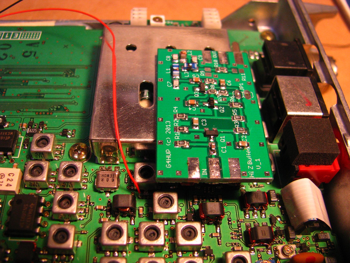
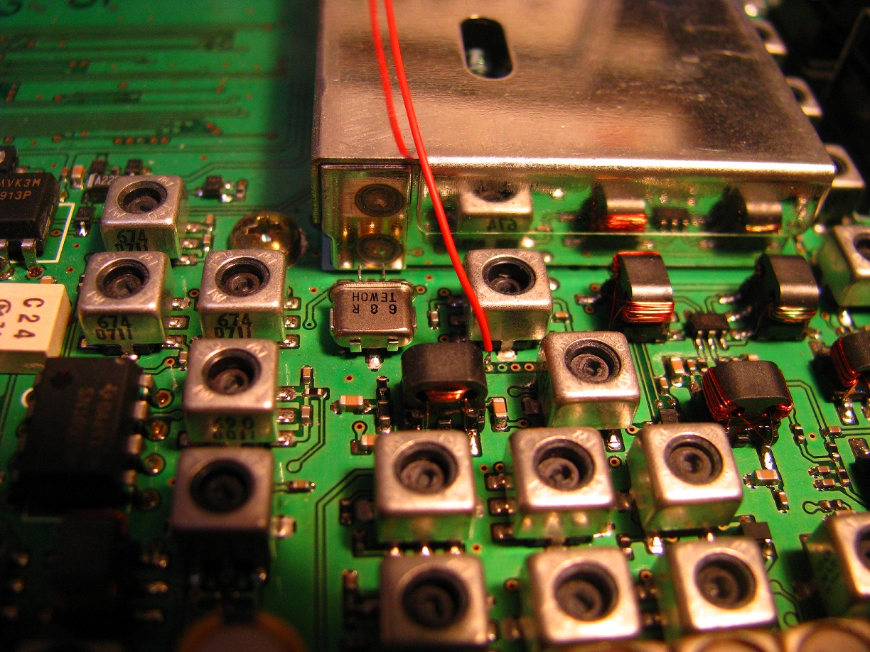
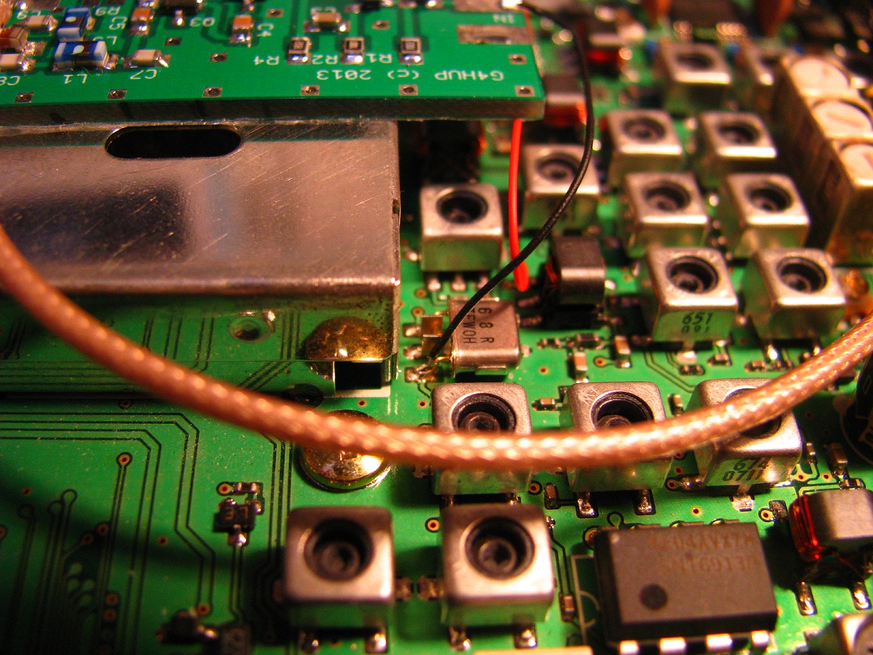
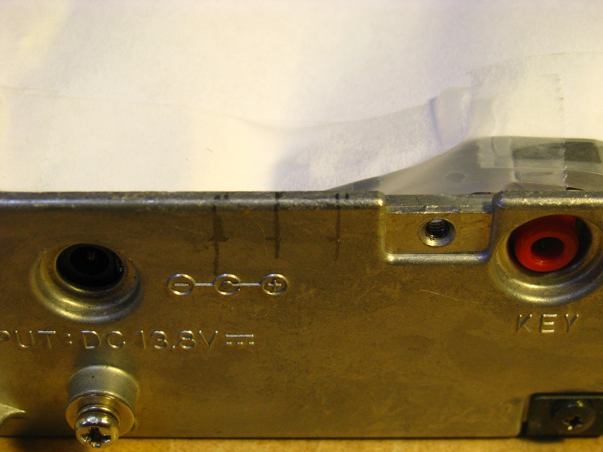
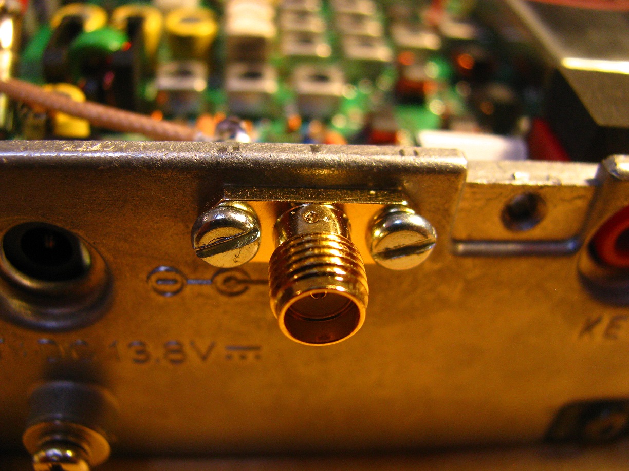
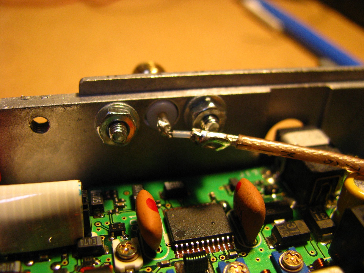
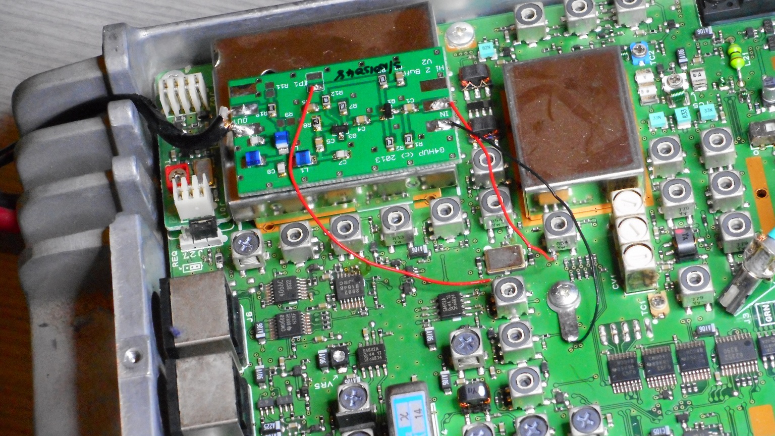
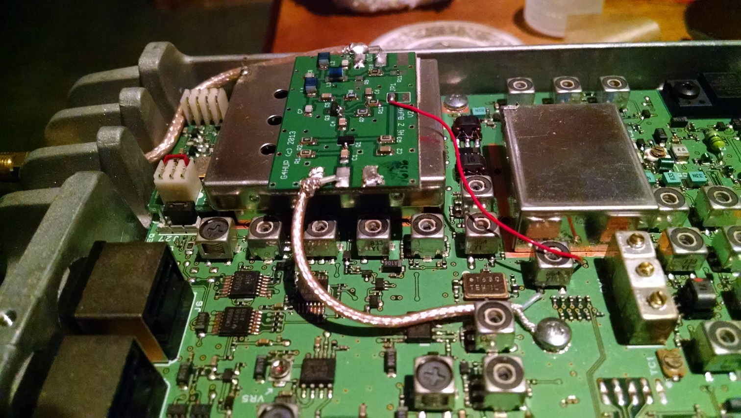
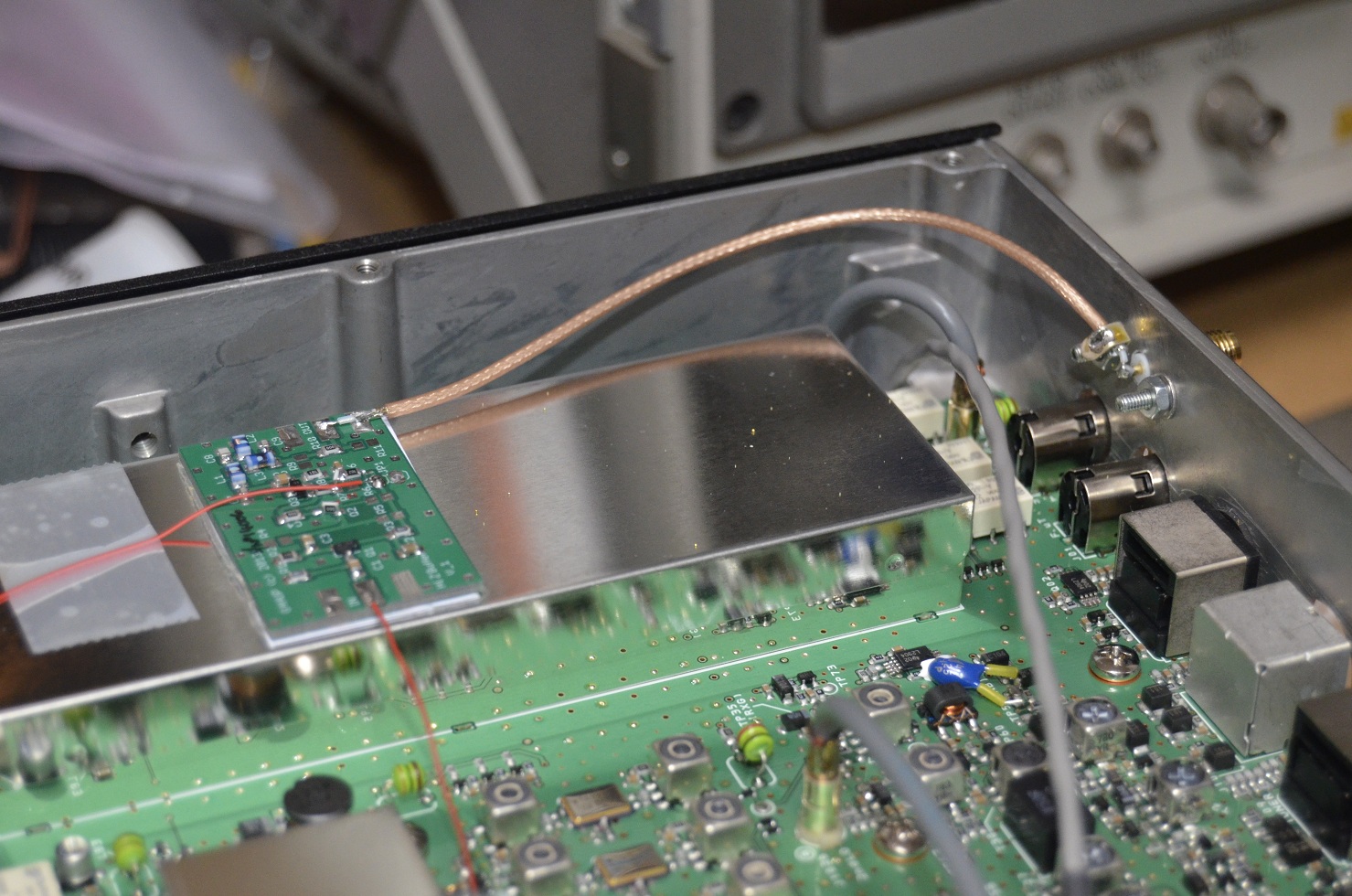
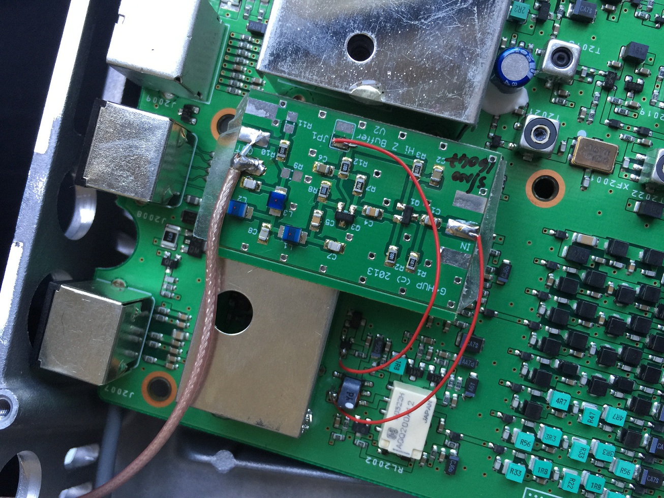
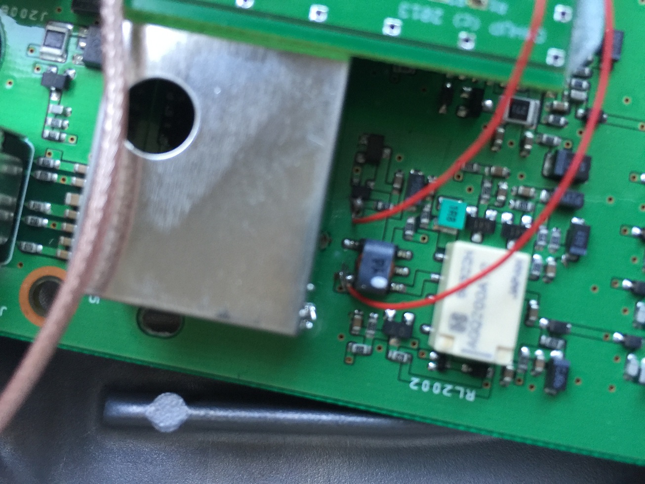
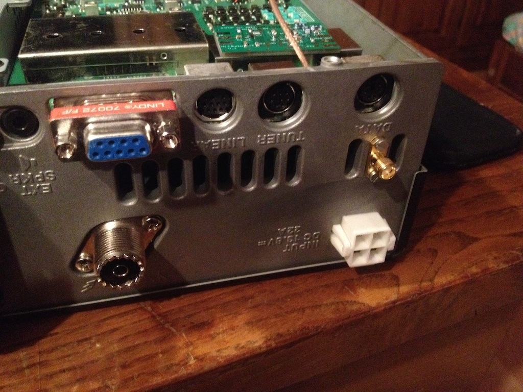
PAT board in place in FT817. Red wire to left is RxB ready to be terminated on PAT boardBetter view of RxB pick up point on main PCBSignal and RxB connections for FT817FT817 rear panel marked out for drillingSMA socket installed on back of FT817Output cable from PAT terminated on SMA socket – FT817. Note how braid is left intact, rather than being formed into a pigtail – this is a better method for PTFE cables.
FT857
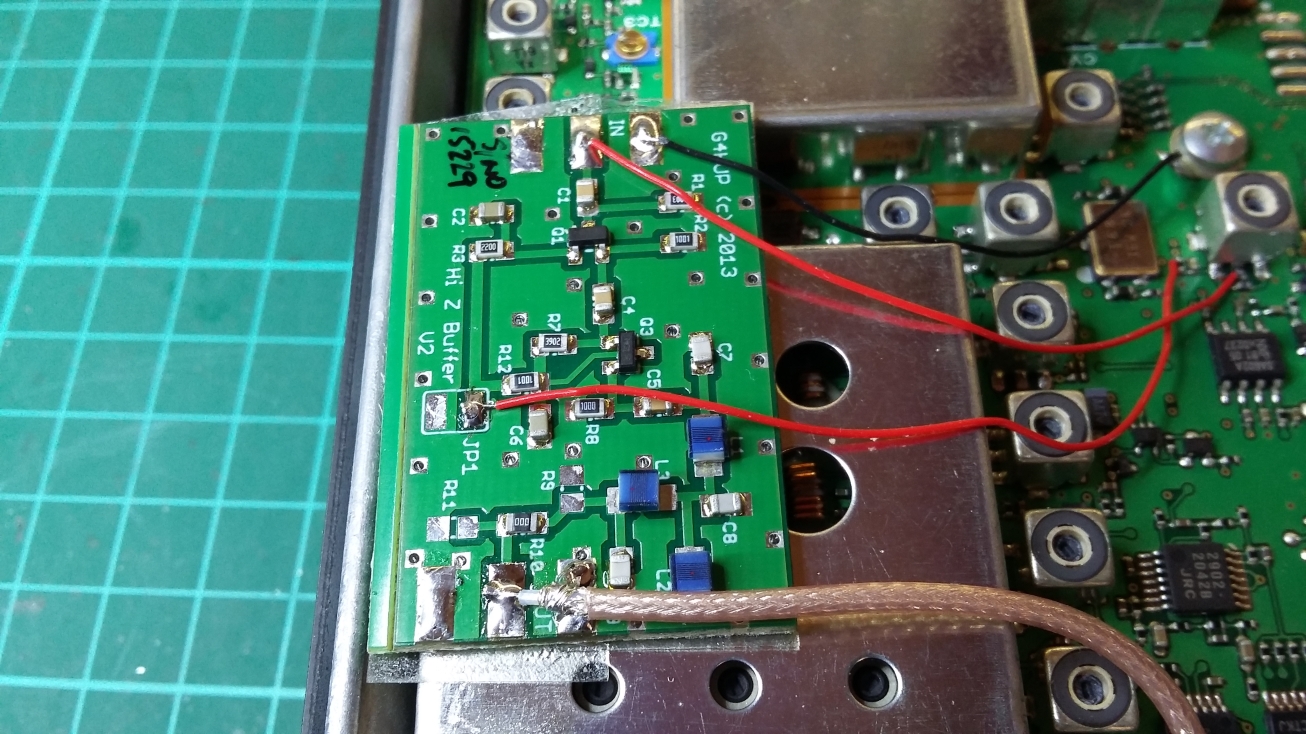
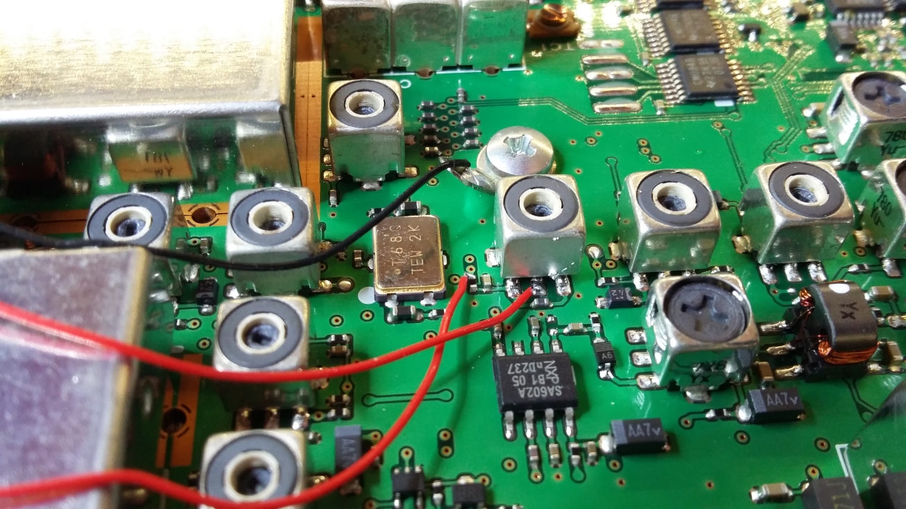
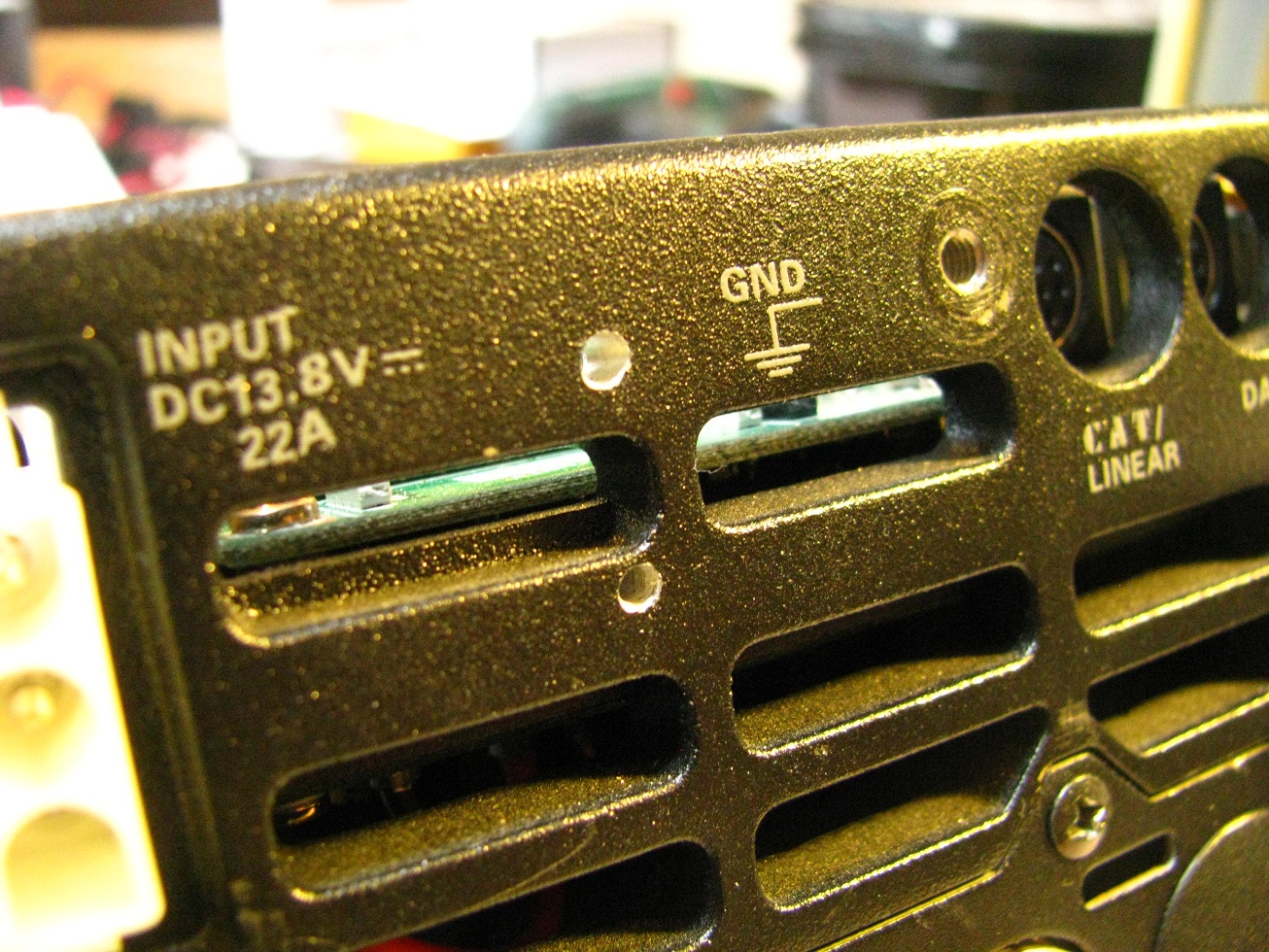
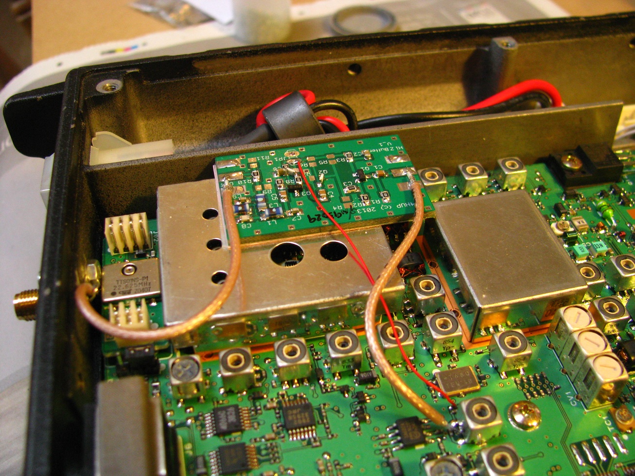
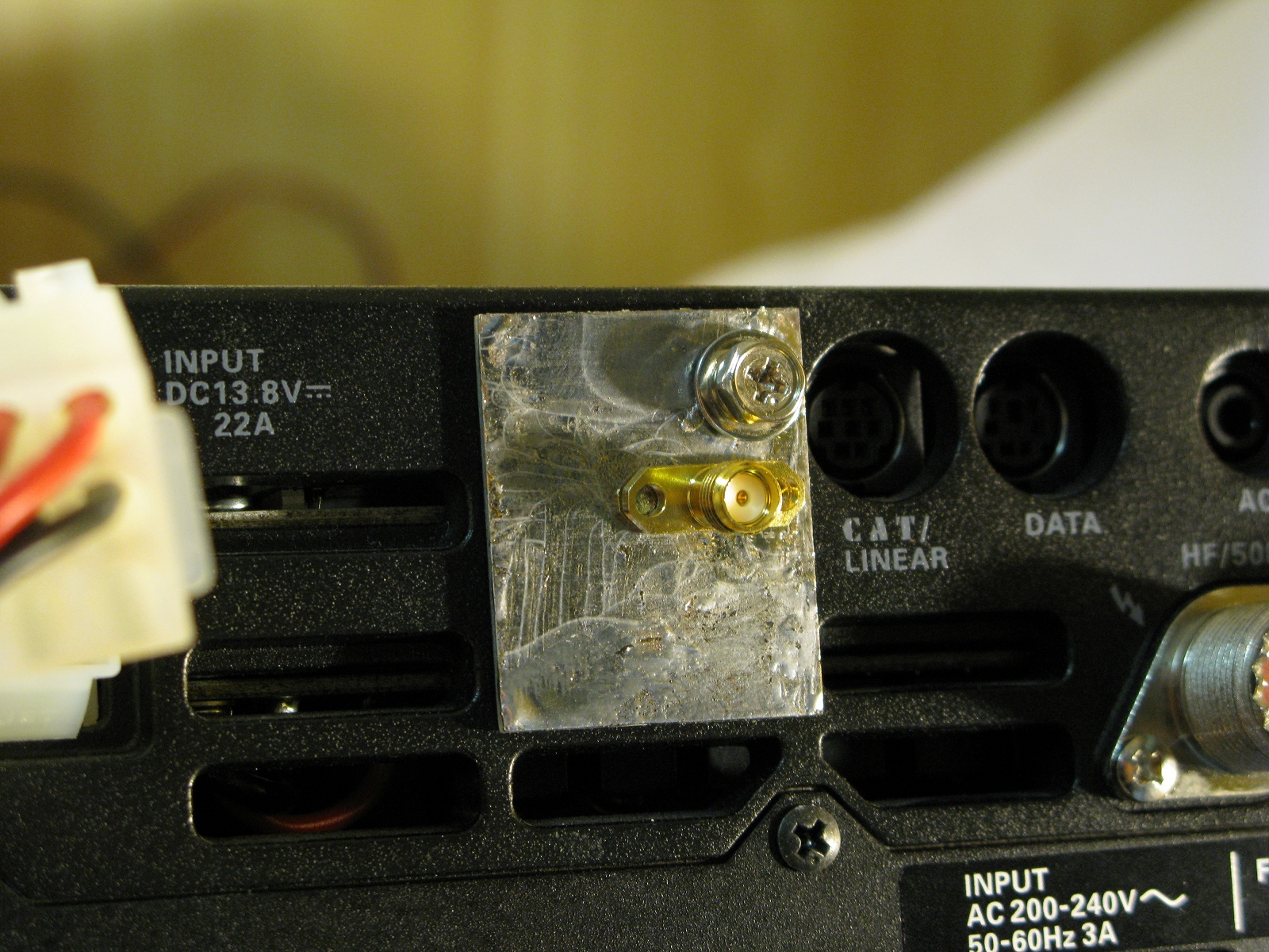
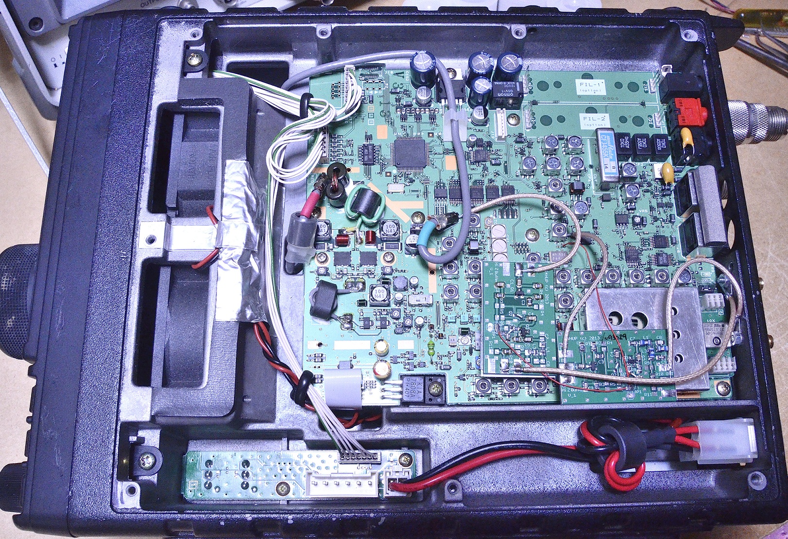
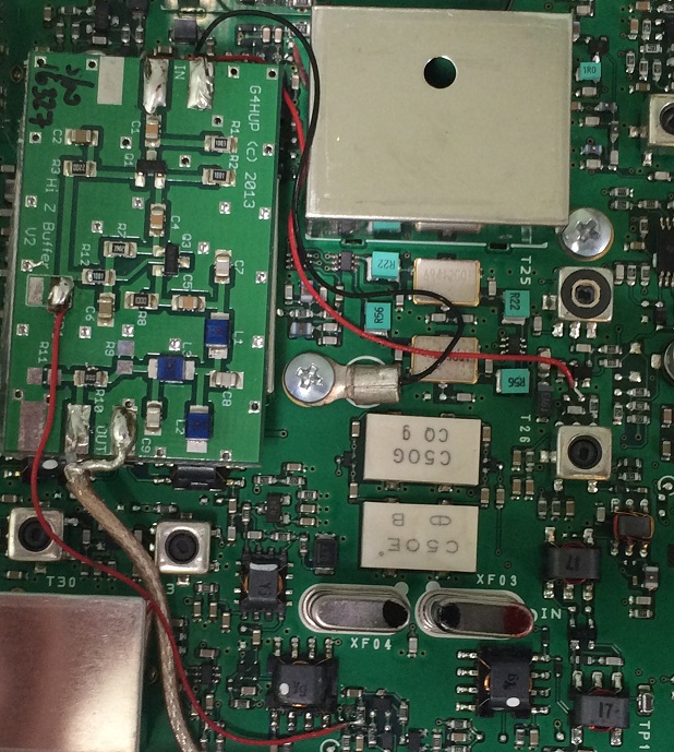
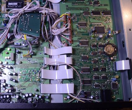
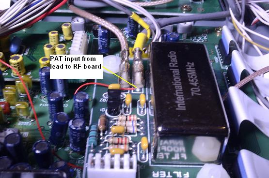
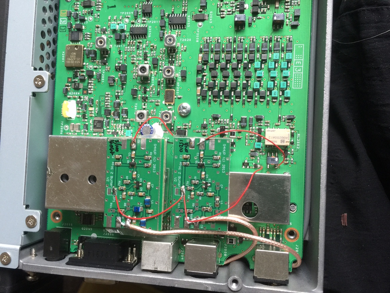
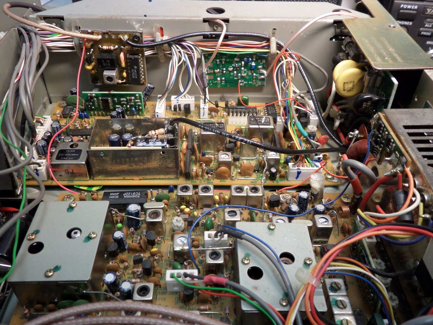
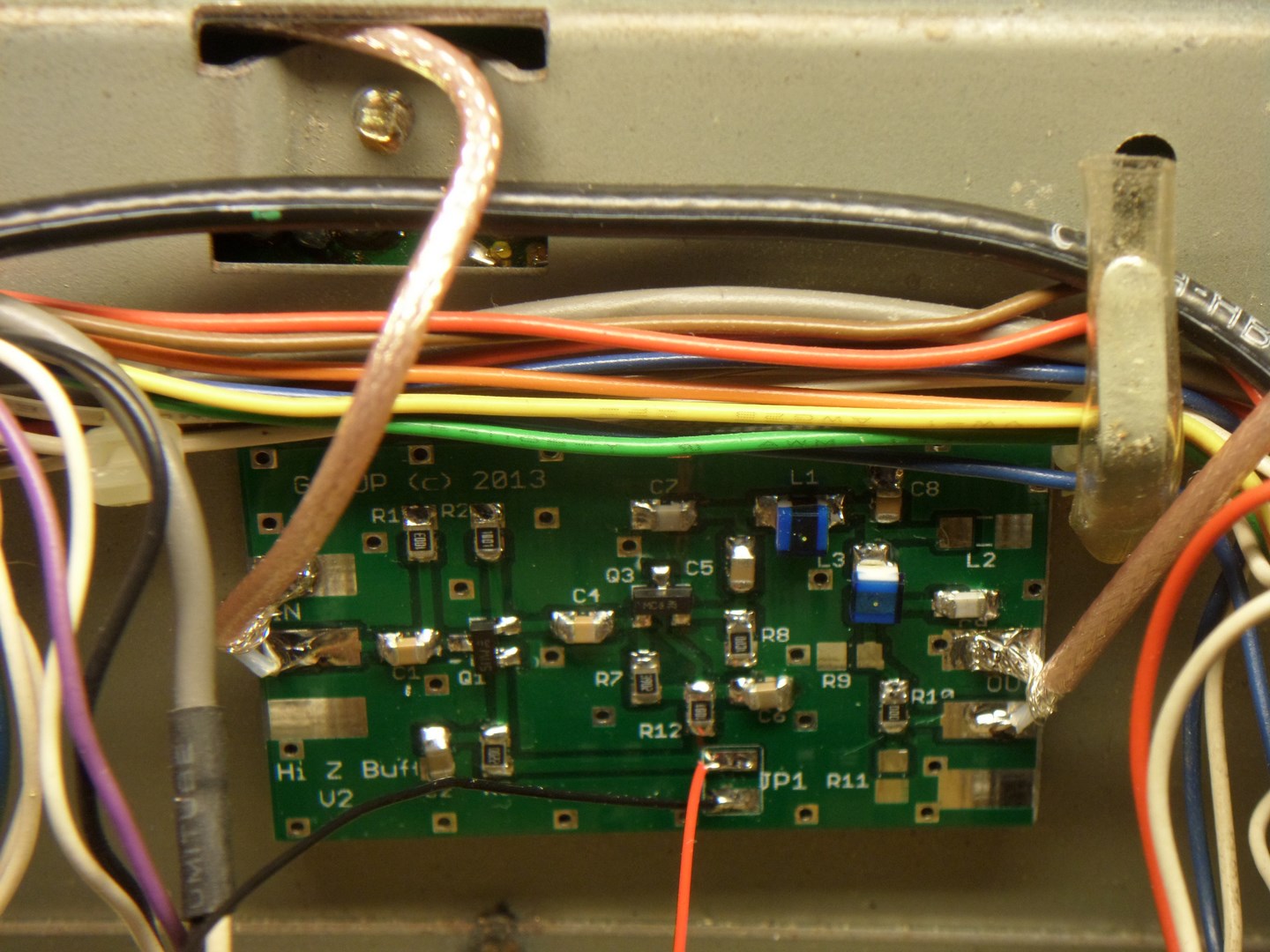
VK5DWC PAT installation in FT857W8XDR PAT installed in FT857. I don’t recommend coax for the PAT input connection as the parallel capacitance is high, and could affect tuned transformers.IZ2ZQG’s mounting of PAT in the FT857Detail of the connection points FT857. Black is Ground, left hand red is RxB and right hand red is PAT input. IZ2ZQG.
I note that all three of these users have decided to mount the PAT board on the same screen can. An alternative may be the one to the right in pictures 1 and 2, which has no holes for core adjustment, and gives a much shorter input connection!
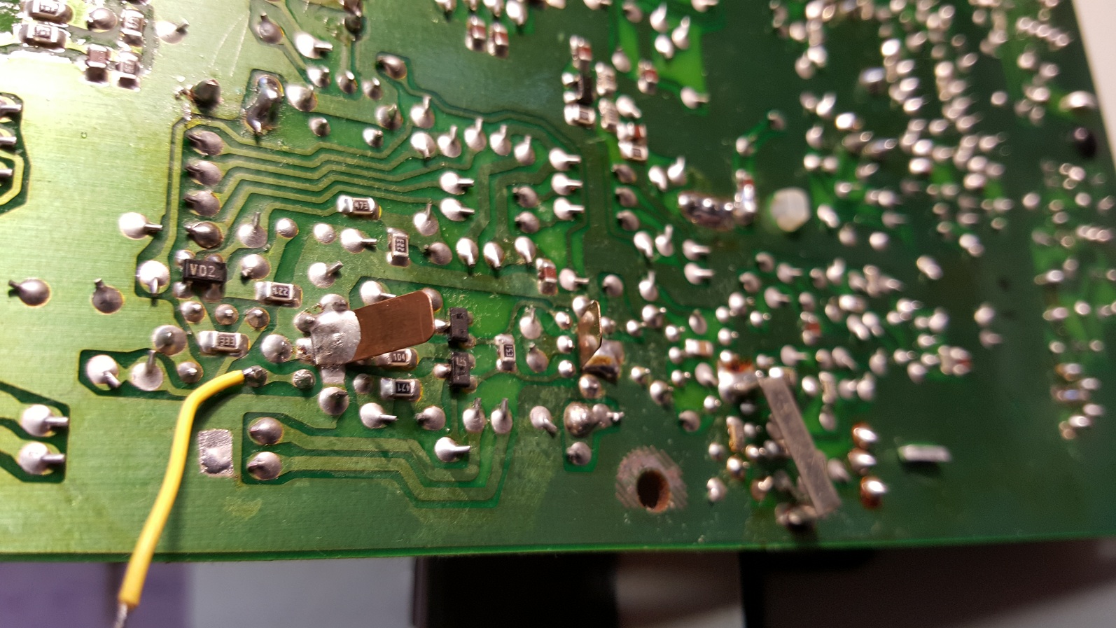
FT897
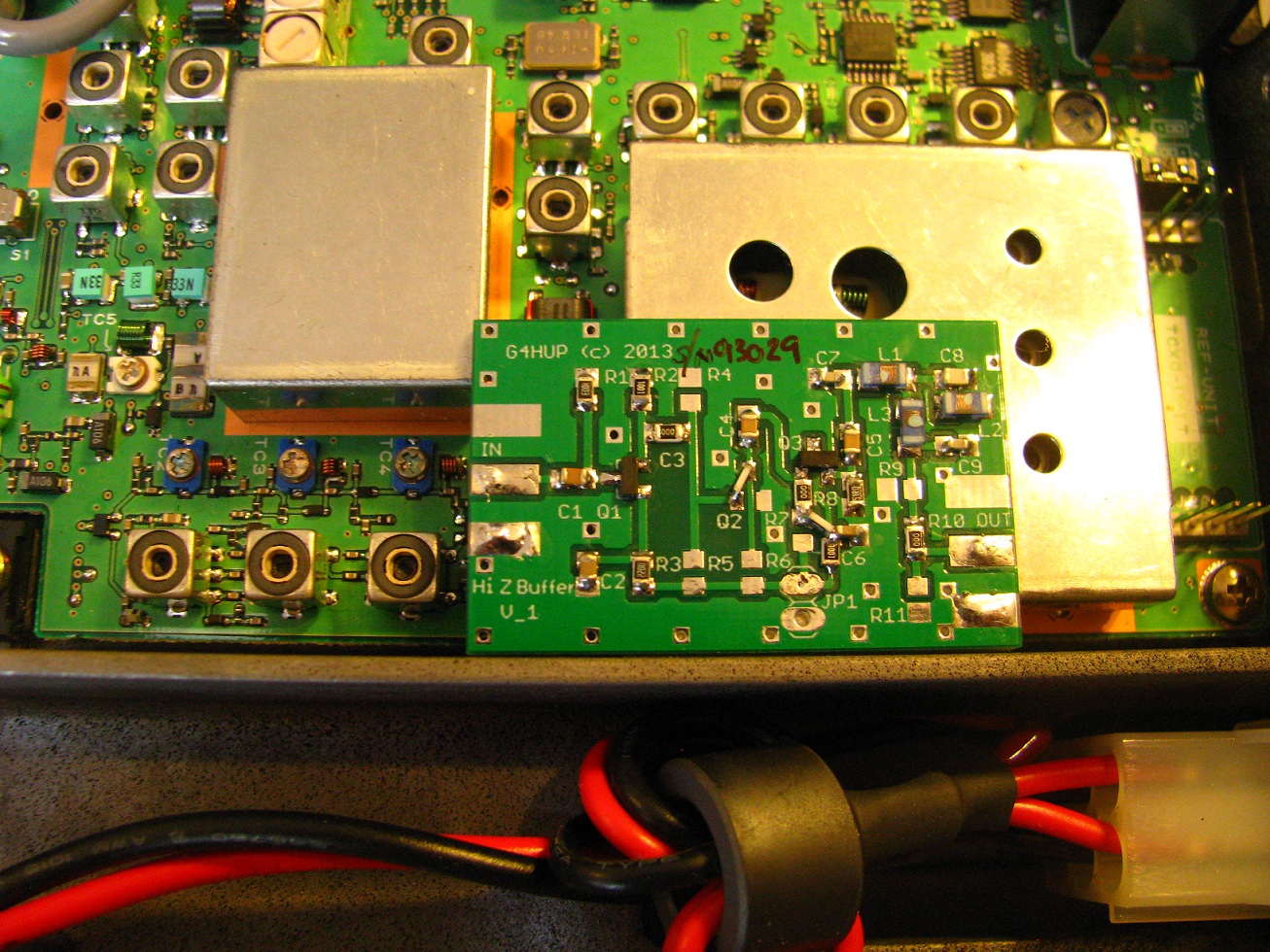
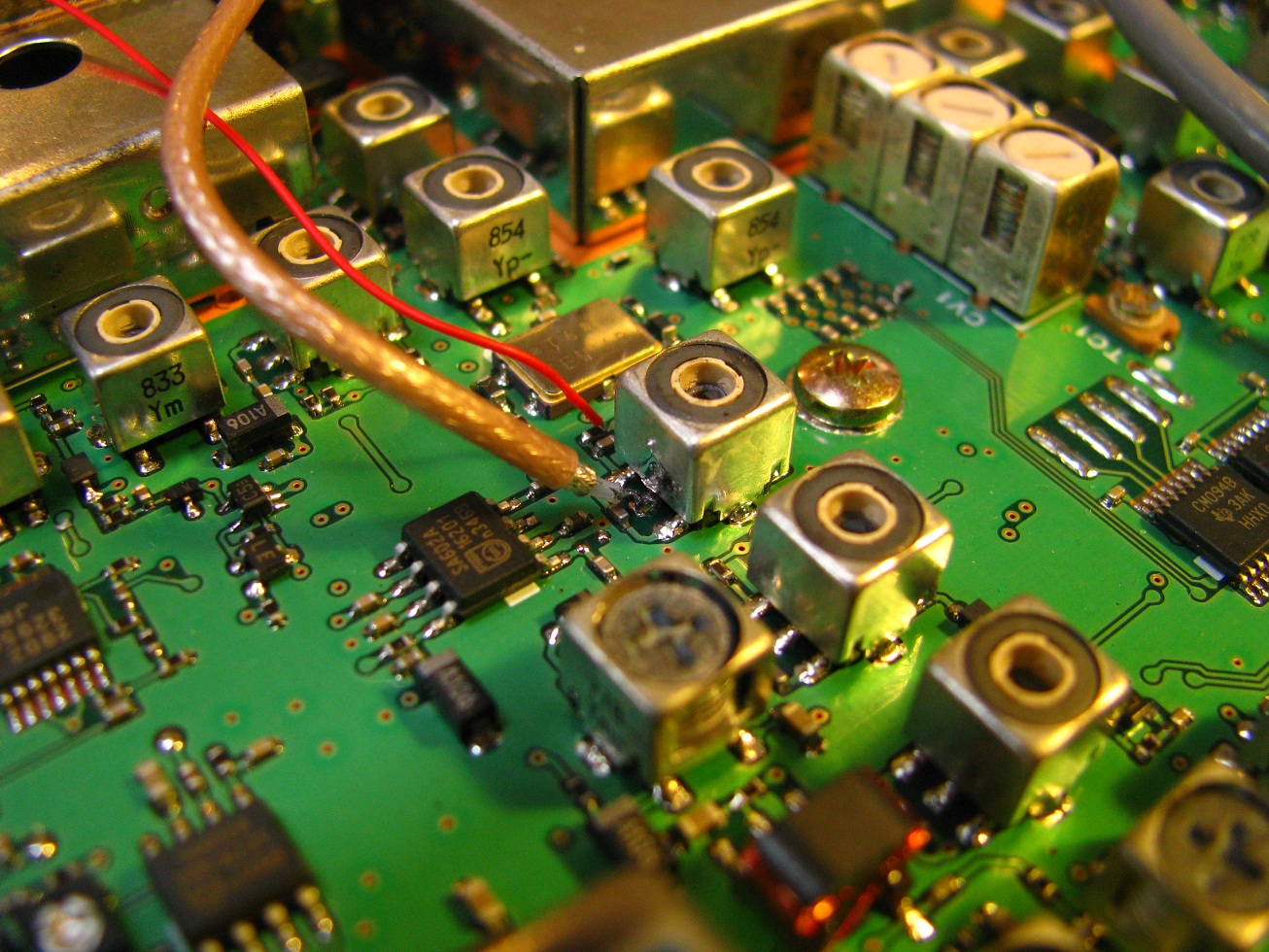
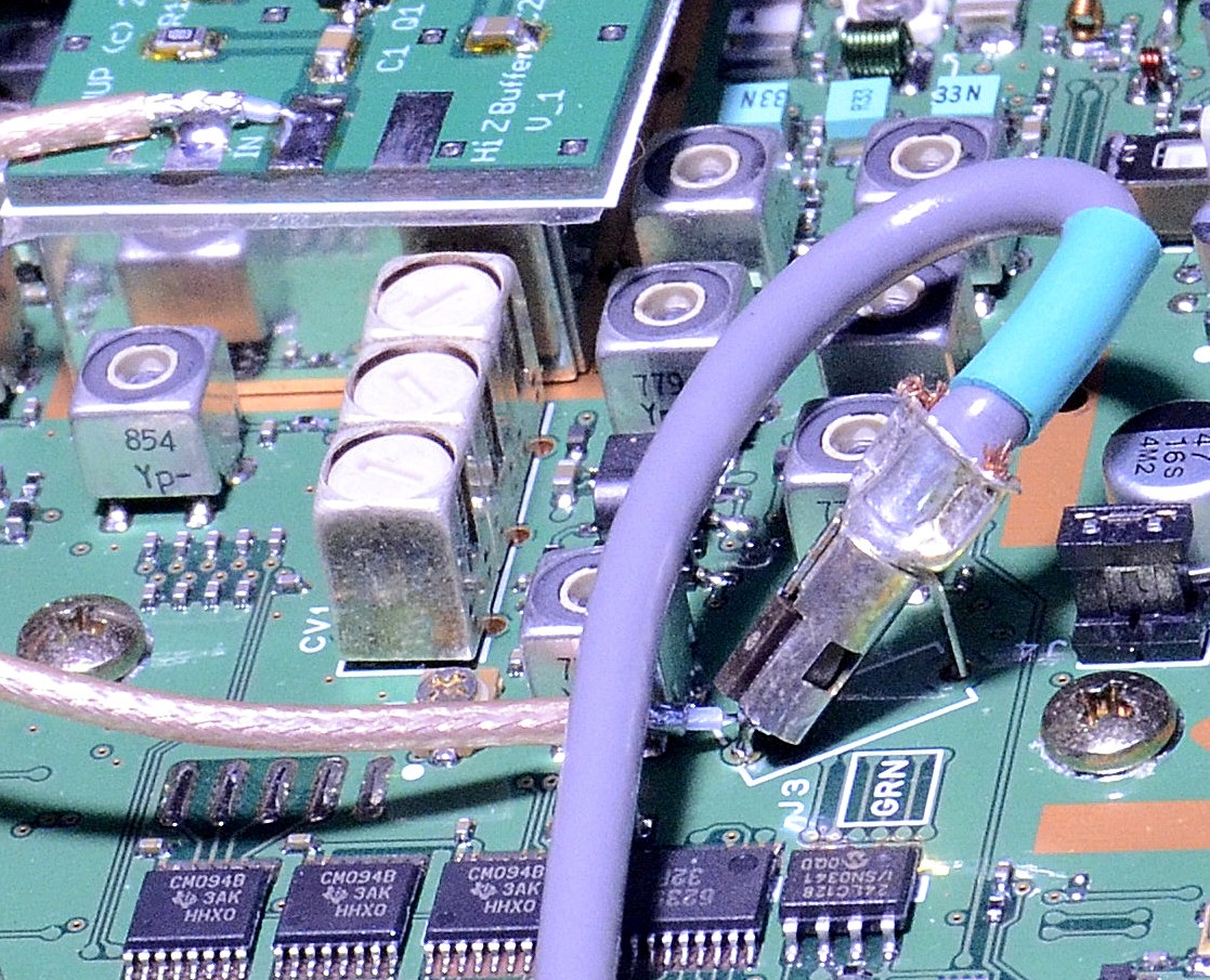
PAT position in FT897 – note this is an early V1 PAT PCBFT897 connection detail for RxB and signalRear panel drilled for SMA socket – note that two holes are different sizes – see the Installation notesGeneral view of FT897 installationF4HCK’s alternative SMA mounting method for the FT897View of 2nd PAT installed. PAT 1 is IF tap, PAT2 is 2nd independent RxDetail of signal pickup for PAT2 in FT897
PAT Connections in FT991 – KU0D
FT991
PAT Connections in FT991 – KU0D
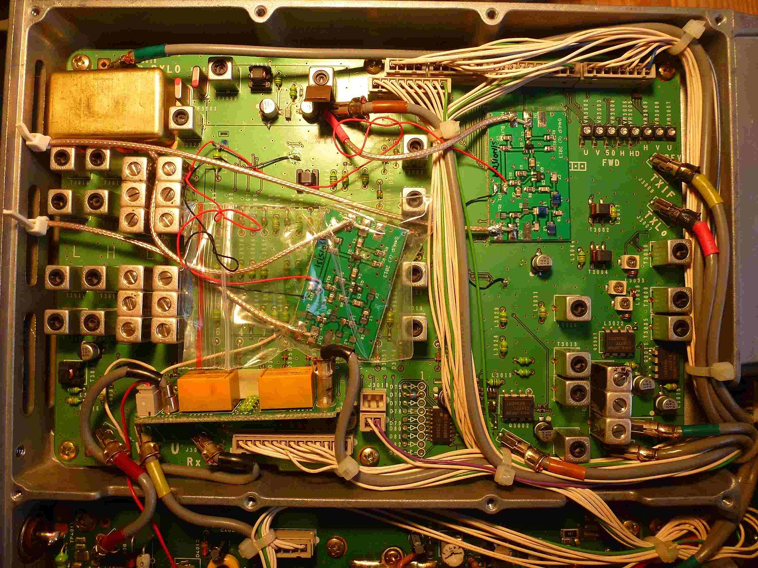
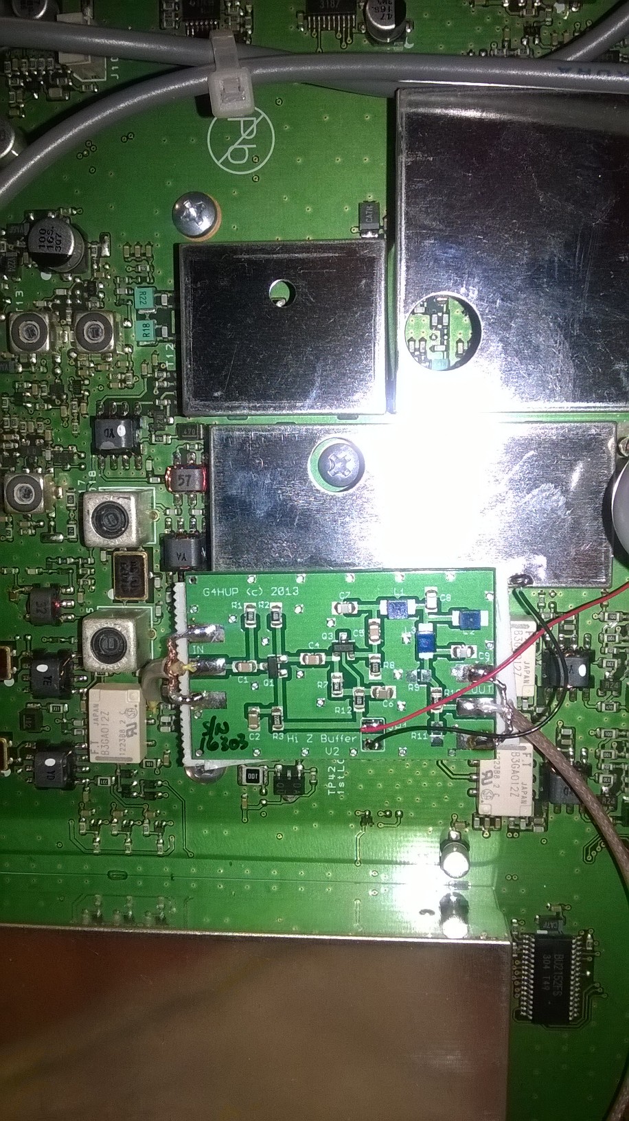
FT847
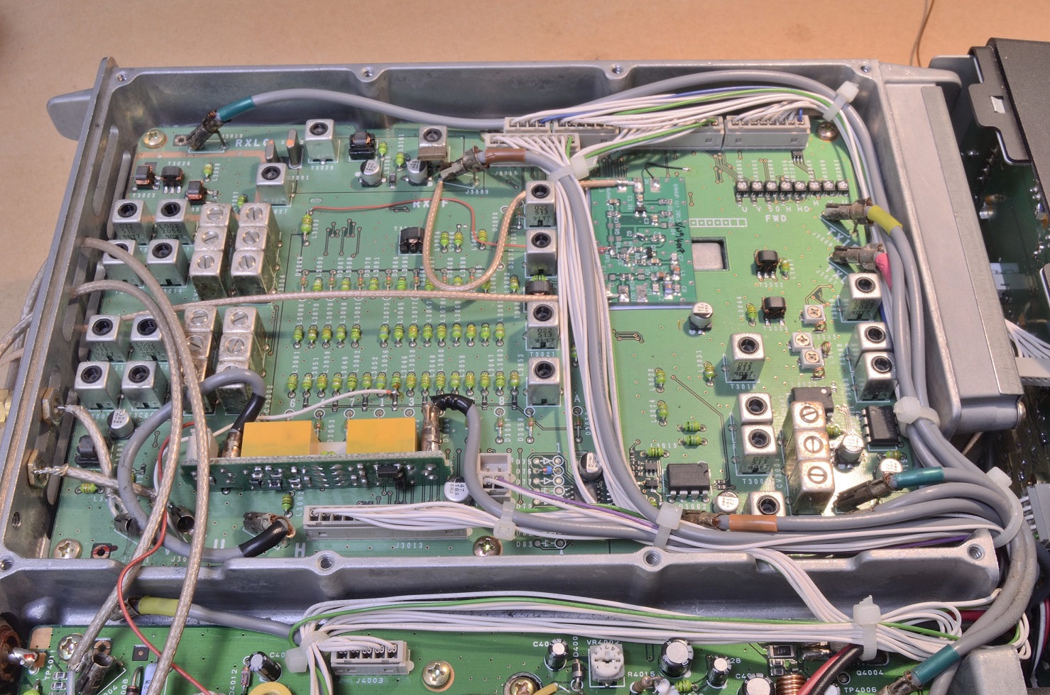
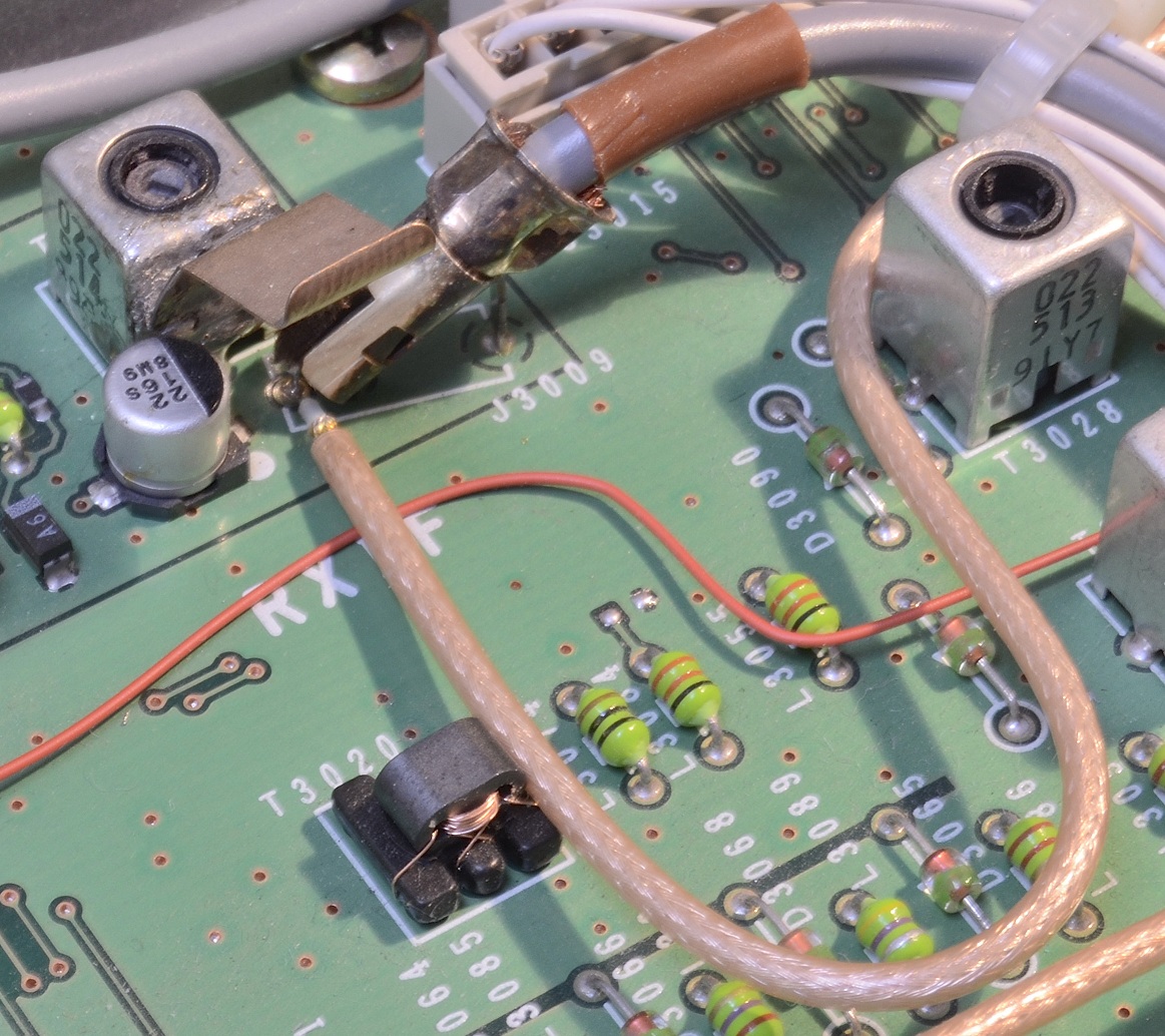
Overview of PAT installation in FT847 – PAT70 acting as IF tapDetail of connection at J3009 in FT847 to pick up input signal for the PATPicking up the signal at the mixer (T3023) for 2nd Rx application. Some FT847’s have a shielding can around the mixer.Alternive connection for 2nd Rx where rig has a shield. PCB must be lifted to make this connection. Info due to M0STODL7AOH removed the can and drilled a hole in the side to bring the cable out. PAT in the plastic bag is a PAT-V for 2nd Rx use.
FTdx1200
PAT location in FTdx1200 de PA0PSAPAT Vcc connection de PA0PSAPAT output via GSIK de PA0PSA
FT1000
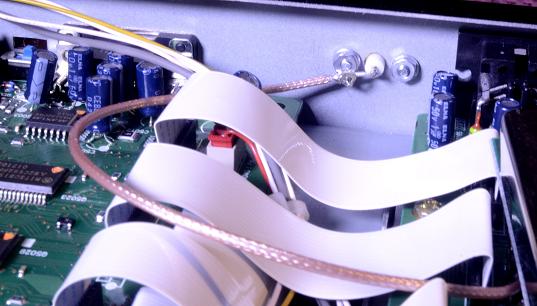
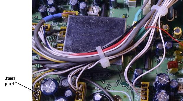
PAT location in FT1000, underneath Filter boardFT1000 PAT input picked up from TMP connectorFT1000 rear panel socket mounting, by DVS-2 connector.
The FT000 RxB line is picked in the wiring loom, from the wire connected to J3003, pin 4.
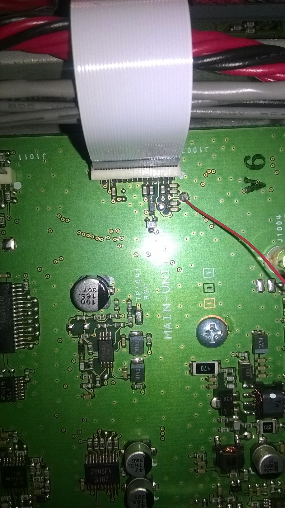
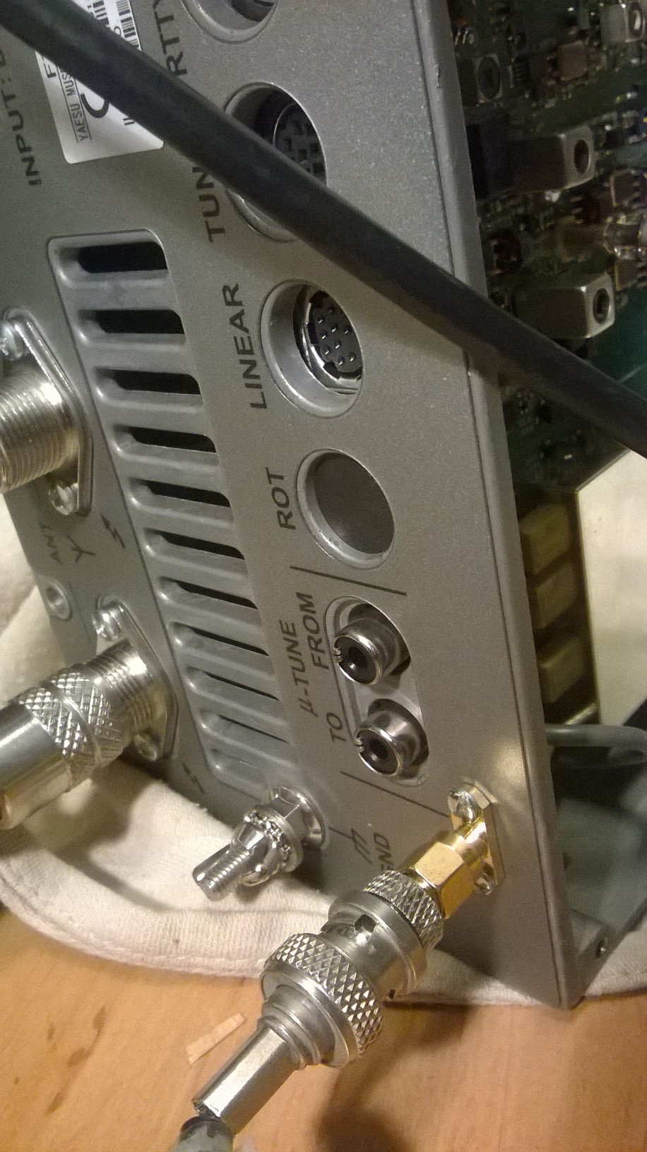
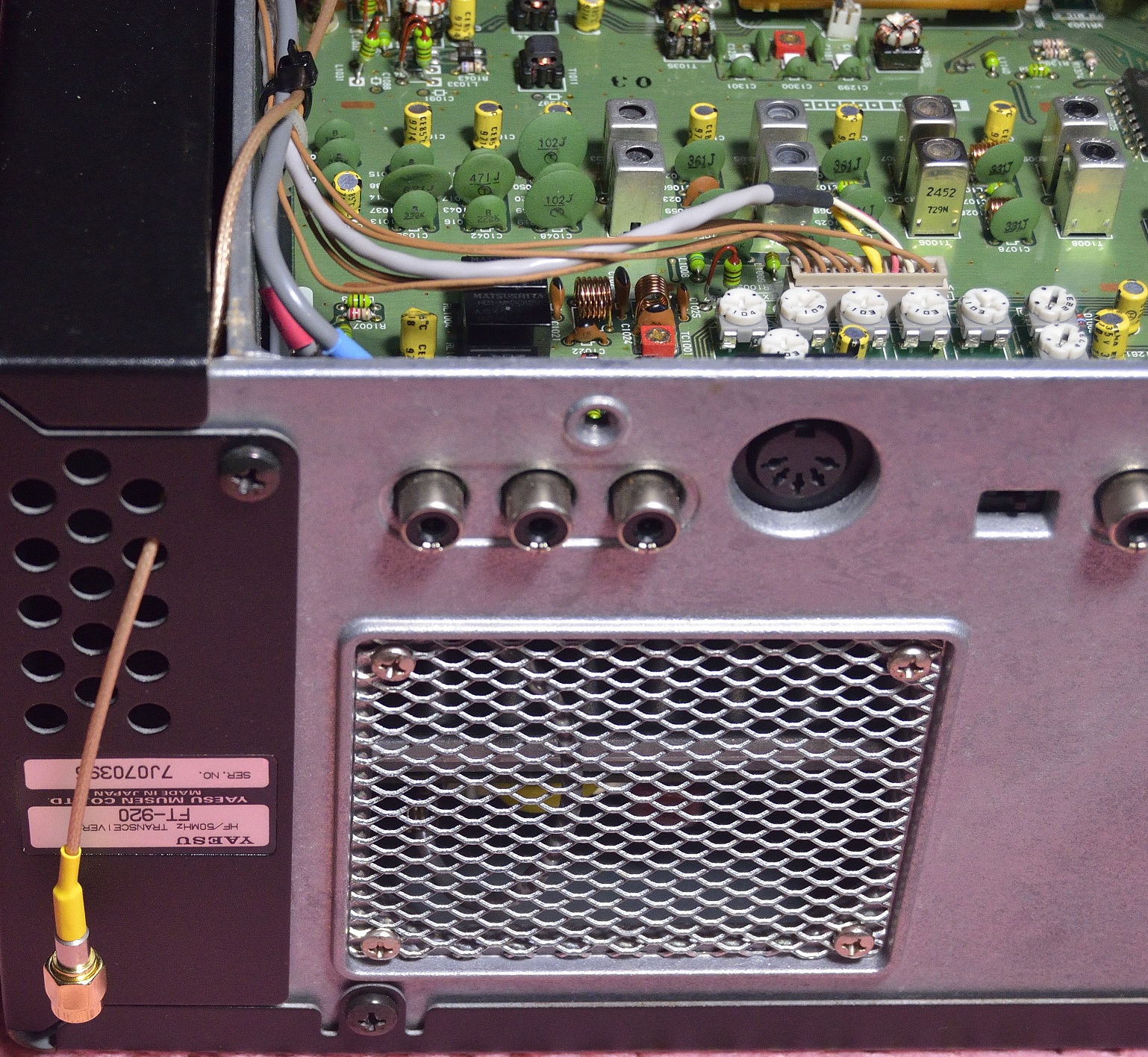
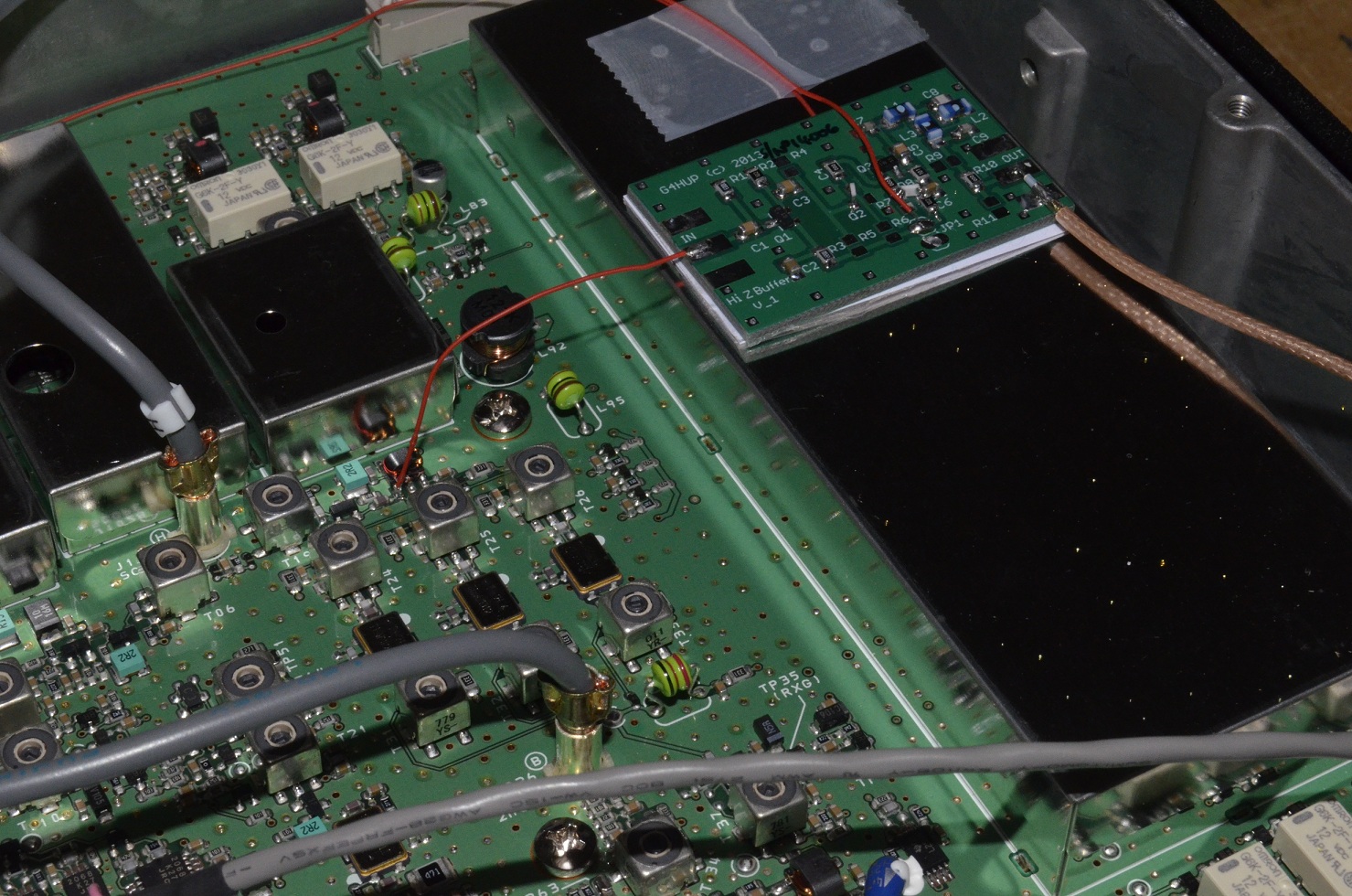
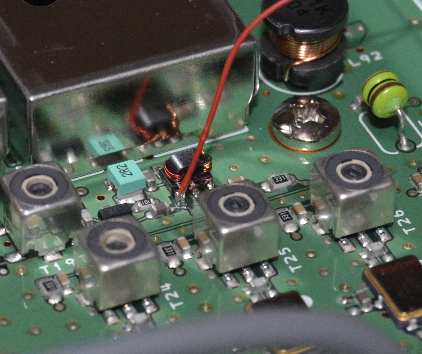
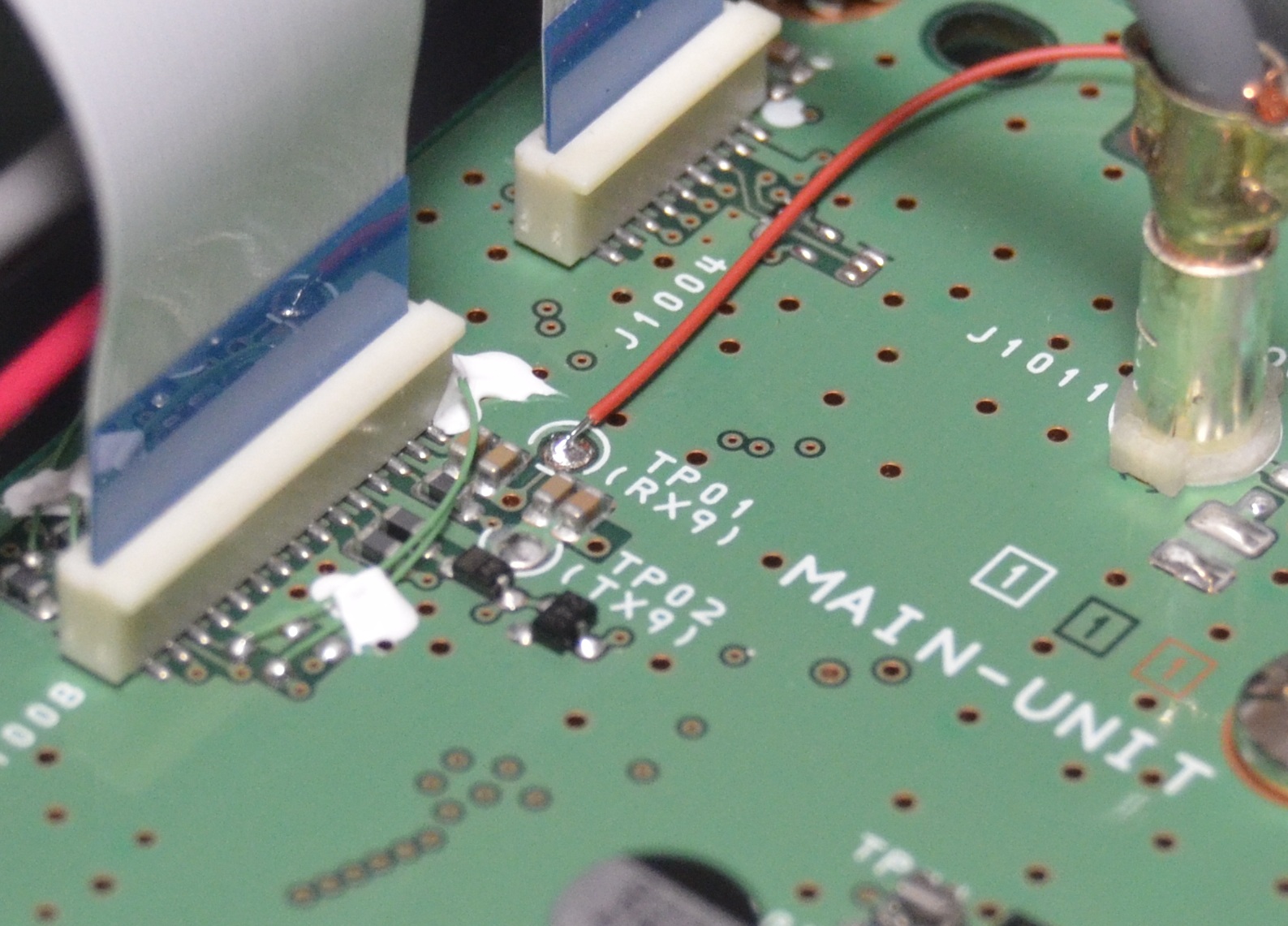
FT920
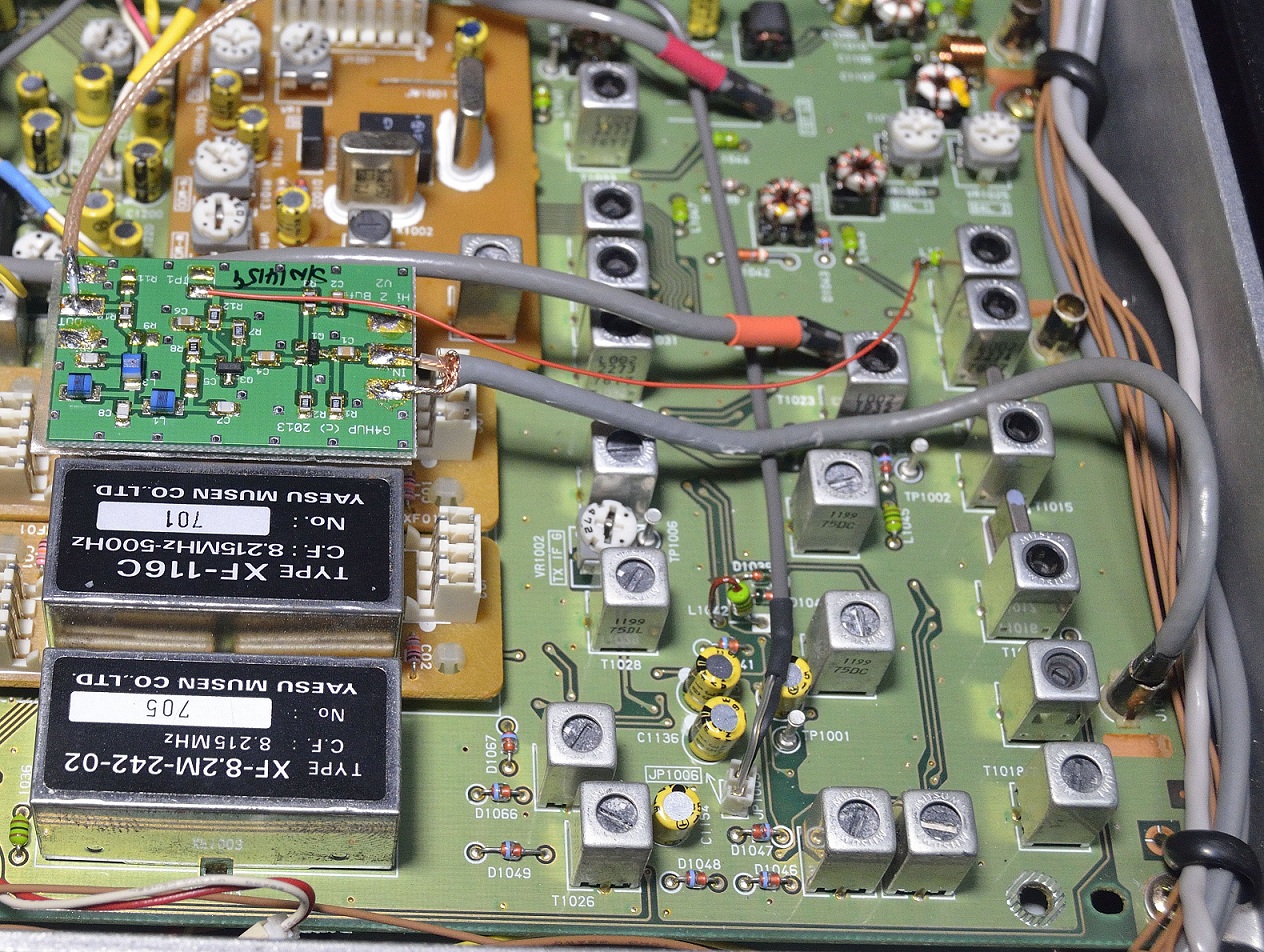
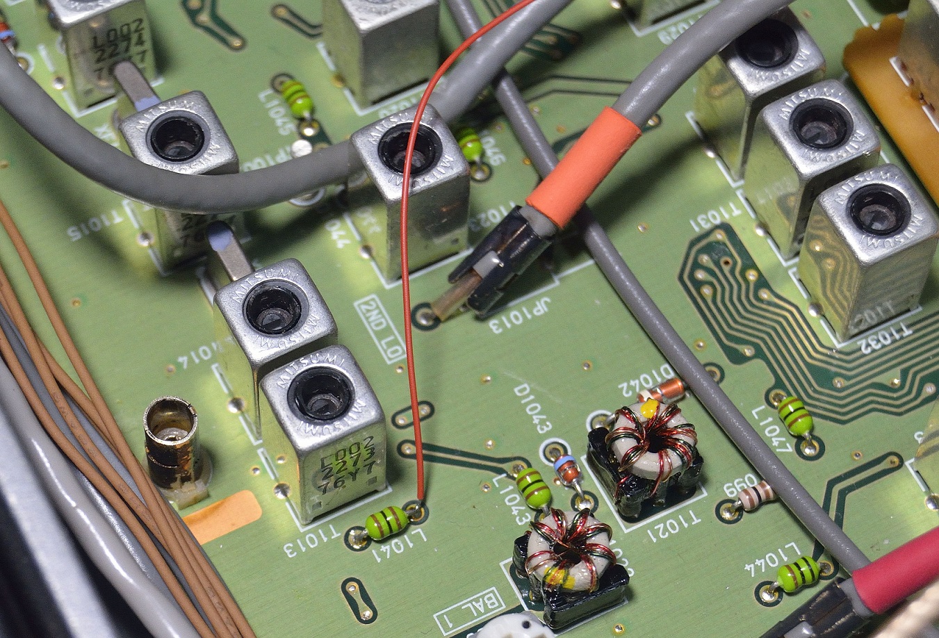
PAT in FT920 showing input pick-up via J1008 (TMP Connector)FT920 RxB pick up from L1041Output cable exit from FT920 via vent holes at side of rear panel.
FT950
FT950 PAT board mounting and input connectionFT950 input connection detailFT950 RxB connection detailFT950 PAT output via SMA socket on rear panel
FT450
FT450 PAT board mounting – 2E0WCLFT450 Connection detail – IF tap – 2E0WCLFT450 Rear panel SMA mount – 2E0WCLFT450 2nd PAT installed for independent Rx function – 2E0WCL
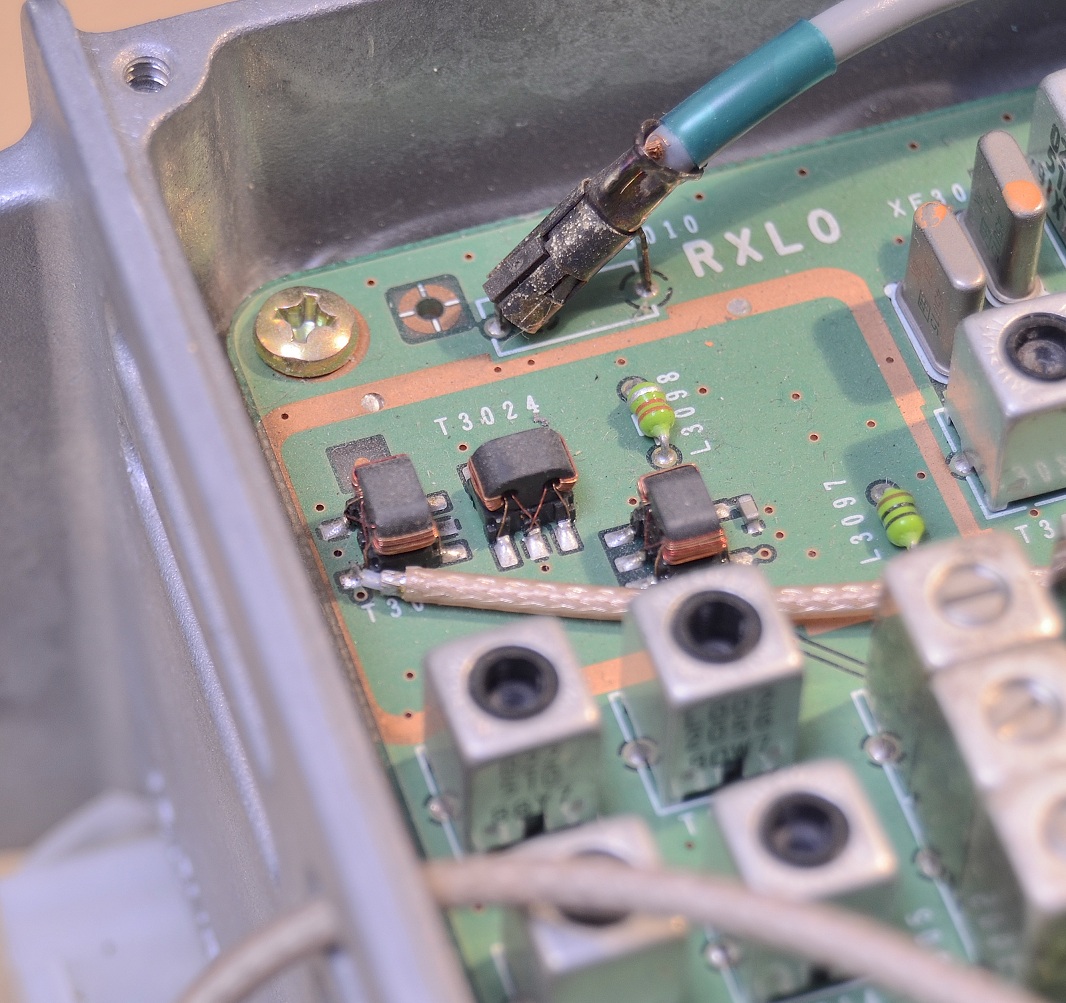
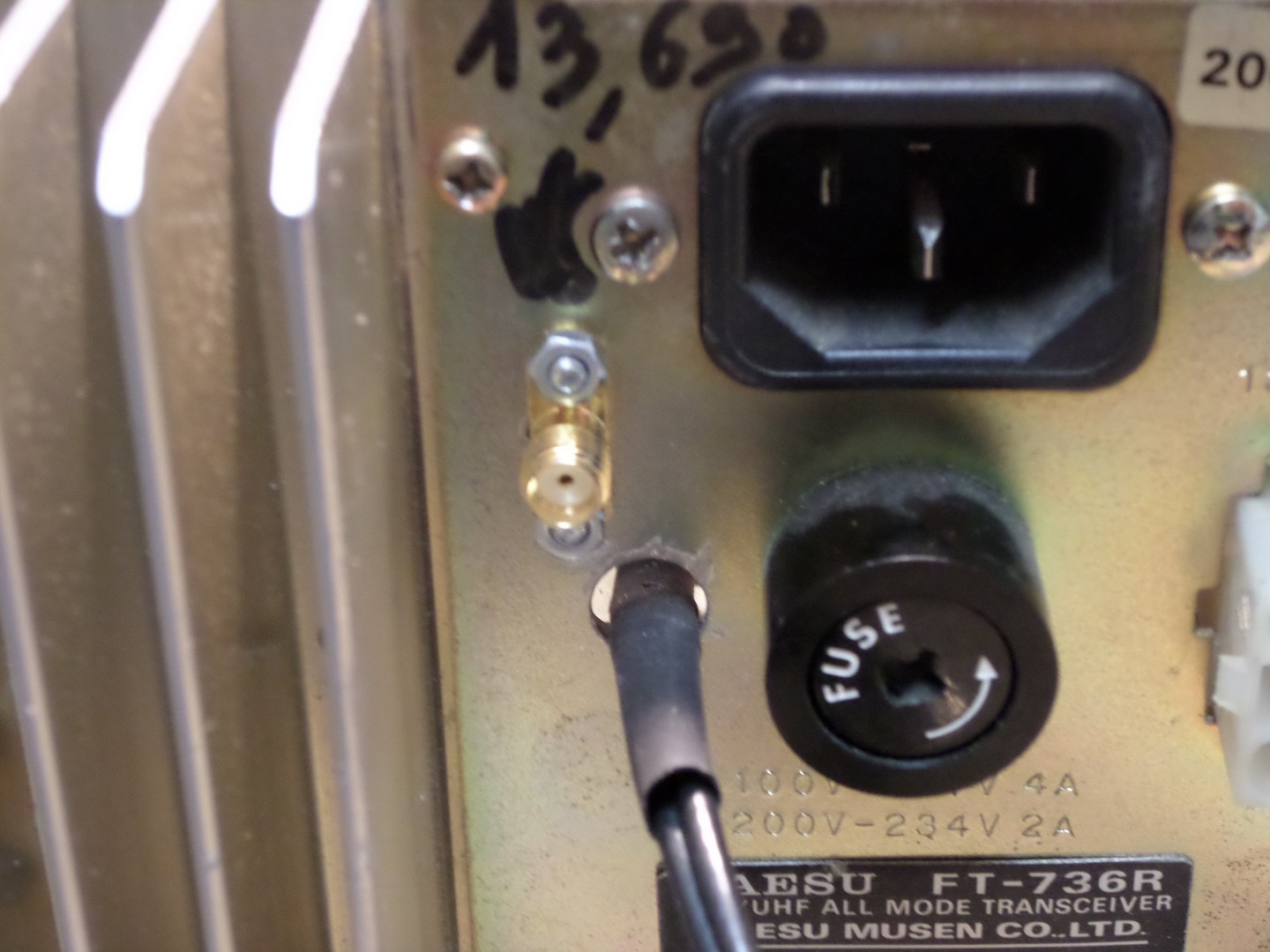
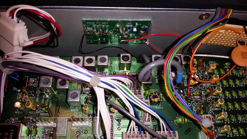
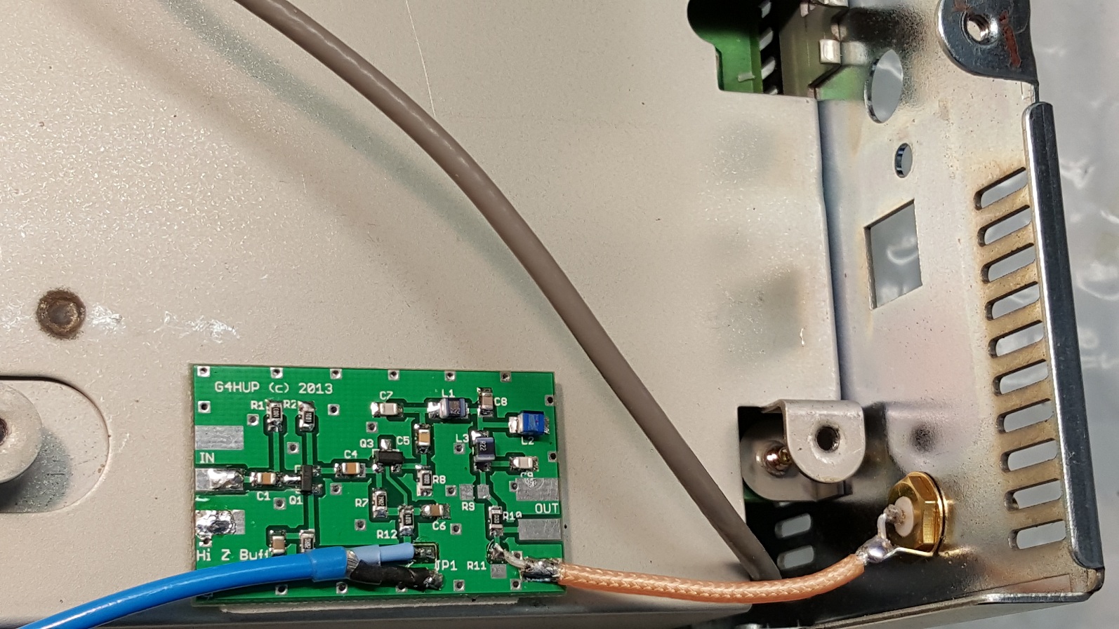
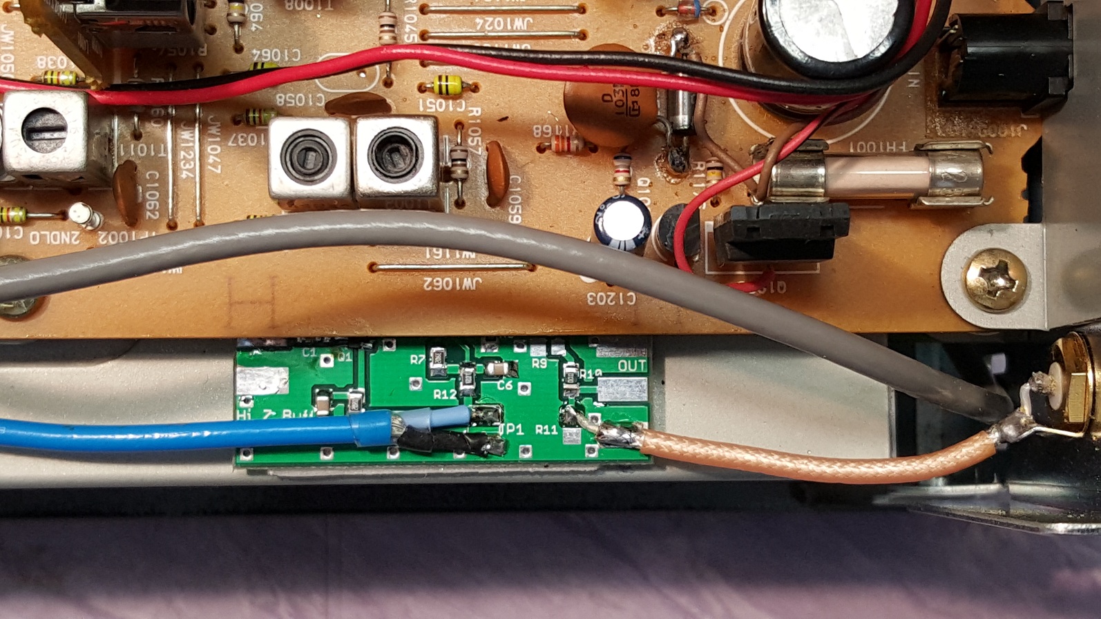
FT736
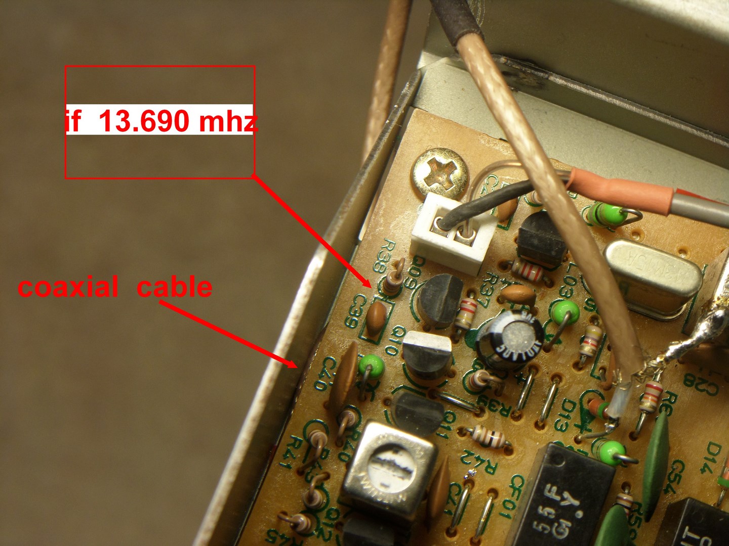
FT736 PAT mounted on side panelFT736 PAT connectionsFT736 pick up detail – note that coax cable shown is NOT the PAT input connection! The 13.69MHz input signal for the PAT can be picked up on the hot ends of R32 or R33, or anywhere between T03 and T04 – see p16 of the FT736 Technical Supplement.FT736 rear panel connector
FT840
FT840 PAT install
FRG-100
FRG-100 PAT in place – main board removedFRG-100 PAT in position – main board replaced.FRG-100 PAT input connection to main PCB