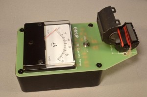
 This kit provides you with a simple but effective means of measuring the current in antenna wires, and of looking for braid currents on coax feeders. The more current you can get flowing in an antenna, the more efficiently it will radiate your signal – so a means to monitor the current is a great aid when making adjustments and setting up antennas.
This meter, using the provided ferrites, is substantially flat in its performance from below 136kHz up to 30MHz. Below 1.8MHz, it is particularly useful, since the traditional HF SWR bridge shows decreasing efficiency as we get down towards 474 and 136kHz. Some measured results on various samples are given further down the page.
The circuit used is based on a design published by Ian White GM3SEK and uses an idea broached by David Lauder, G0SNO, of the RSGB EMC Committee, in using a clamp-on EMC ferrite for the current transformer. Although these are intended for suppression of unwanted potential EMI components, they do make very good current transformers for measurement purposes up to 30MHz, and will continue to give useful relative indications well into the VHF region. Further information, beyond the construction and use notes here can be found on Ian’s webpages.
The RF Current Meter Kit Manual is here.
Measured Performance Results
1. Basic Measurements – overwound transformer secondary.
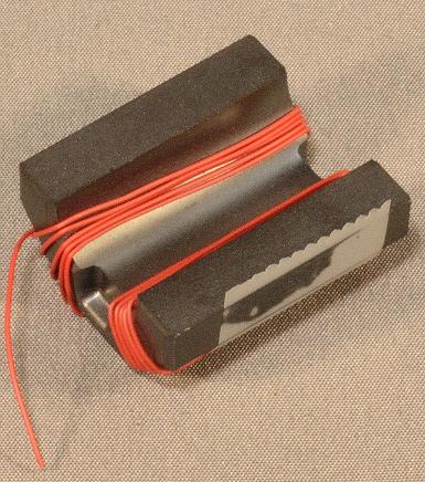
These measurements were made on one of the early samples, where the transformer secondary was wound over the outer plastic case of the clamp after it had been glued to the PCB. The source was my FT897, via the test cable (as shown in the Manual) into a dummy load. The readings given are simply taken from the power output displayed on the FT897, so do not represent ‘lab quality’ measurements.
It can be seen that the efficiency of the transformer is steadily decreasing as frequency increases, as higher power is needed to achive FSD. However, the increase is small from 160m to 10m, so it can be considered as a flat response. Due to the response of the diodes, the scale is not linear, and with around 40W giving an indicated current of 1A, 5W of forward power is giving around 0.2A indicated. According to theory, 50W of forward power should give a current of 1A. Measurements were not made on the 100mA scale, as the FT897 power level cannot be reduced below 5W on the HF bands.
2. Basic Measurements – internally wound transformer secondary
These measurements were also made on an early sample, where the transformer secondary was wound over the ferrite core half only, after removing it from the outer plastic case of the clamp. The completed assembly was glued to the PCB once wound. Again, the source was my FT897, via the test cable (as shown in the assembly notes) into a dummy load, hence the same limitations apply as in the table above.
As a comparison with the first set, these measurements show a much more consistent performance across the HF range, no doubt due to the better coupling. An added advantage of this method is that the secondary winding is better protected, since the turns are entirely enclosed within the clamp.
3. Lab Quality Measurements
G4FRE has also measured the performance of a sample, including the LF bands which I am not equipped to do. He has used lab quality equipment, and therefore more credence can be attached to the power levels in this table. This sample also used a secondary that was internally wound.
These results shows power levels for FSD that agree more closely with theory on both the 1A and the 0.1A ranges. The response shown is still acceptably flat from 136kHz right up to 30MHz.
Test equipment
– HP436A Power Meter with 100kHz to 4.2GHz head,
40dB coupler
|
|
|
|